General Specifications: Maximum Temperature 350ºF (177°C), operating Voltages (dependent on power supply) range +0 +450V DC, Current consumption at 200V 15mA, Tool Bus data rate 115kbps, Wireline Uplink data rates currently 12 kbps to 67 kbps, and Downlinks rates 1 kbps to 5 kbps. Input Voltage Requirements are typically +15Vdc, -15Vdc and +5Vdc.

The STB consists of 5 main functional blocks as shown in the block diagram below:
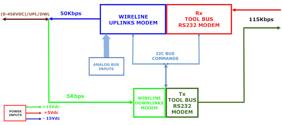
The Wireline Uplink Modem forms the hardware interface between the Rx Tool Bus RS232 Modem and the Wireline mono-cable which transmits data to the surface system. Uplinks are modulated onto the line as pulsed RS232 at a selectable bit rate currently ranging from 12 kbps to 67 kbps with amplitude of +/- 15Vpk. The Wireline Uplink Modem rate can be changed via downlink command. The Wireline Uplink Modem uses half duplex transmission.
The Rx Tool Bus RS232 Modem forms the hardware interface between the Downhole Tools and Wireline Uplinks Modem. Rx is modulated TTL input (5Vdc), onto Rx Tool Bus RS232 Modem at 115kbps. The Rx Tool Bus RS232 Modem rate can be change for downlinks commands via I2C Bus.
A half duplex downlink allows the user to configure and control operations from the surface prior to and during logging. Control is exercised by means of commands, which may be destined for the Wireline Downlink Modem, Rx Tool Bus RS232 Modem, and /or passed on to other tools via the Tx Tool Bus RS232 Modem. Where command execution generates a response, this is generally uplinked to the surface via Wireline Uplinks Modem, downlink status is monitored and reported by the system.
The Tx Tool Bus RS232 Modem forms the hardware interface between the Wireline Downlinks Modem and the Downhole Tools. Tx is modulated TTL output, onto the Tool Bus as RS232 at 115kbps (5Vdc). The Tool Bus rate can be changed for downlinks commands via I2C bus.
The Analog Bus Inputs received signals between 0 to 4 VDC. The Tool Head Voltage, Internal Downhole Temperature, and Tool Bus Voltage are sensed and sent to the surface to facilitate setting the appropriate operating voltage.
SDS Simple Telemetry Board Specification:
| Parameters: | Values: |
|---|---|
| Uplink Data Rate over Wireline | 50 Kbits/sec (on most cables); actual rate controlled from surface |
| Downlink Data Rate over Wireline | 5 Kbits/sec |
| Tool Bus | RS232 serial port at logic levels (3.3V to 5.0V); rate configurable but aggregate must be lower than the selected wireline rate. |
| Power Requirements | Plus/minus 12VDC to 15VDC and +5VDC |
| Temperature Rating | 177°C (350°F) for 1 hour |
| Board Dimensions | 7.5 inches x 1.25 inches |